
Why we use jumpers inside RIGblasters
The most frequent inquiry we get at our Tech Support Desk here at West Mountain Radio is "I have been using my RIGblaster with an XXX Radio and have now purchased a YYY Radio, what cables do I need to get to use my RIGblaster with my new radio?"Our answer is almost always the same "You do not need any new cables, you already have the cables necessary to use the RIGblaster with the YYY radio. All you need to do is change the jumpers from the XXX jumpering diagram to the YYY jumpering diagram." There are a few exceptions to this, but we will cover these elsewhere on our Support Pages.
We designed this flexibility into the RIGblaster so you could change radios without having to buy anything new and to make the transition as easy and quick as possible.
If you look at the pinout of the wires in the microphone cable of your radio you will see that each does a specific function.
Here is just such an example from the Icom IC-756PROIII Owners manual;

Figure 1
Four of these lines are needed to enable the RIGblaster to do its thing. They are Microphone input, Microphone ground, PTT and PTT ground. On the jumpering diagrams for a RIGblaster they a referred to as MIC, MIC GND, PTT and PTT GND. The other microphone lines are not needed by the RIGblaster circuitry and are therefore passed straight through the RIGblaster and onto the radio.
Inside every RIGblaster there is a jumper block that looks something like this;
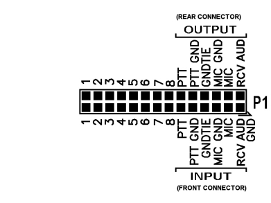
Figure 2
On this jumper block the pins numbered 1 thru 8 on the OUTPUT side represent pins 1 thru 8 of the RIGblaster output to the Radio's Microphone connector and the pins numbered 1 thru 8 on the INPUT side represent pins 1 thru 8 of the Radio's Microphone connector. Therefore referencing Figure 1 & 2 above and assuming we will be developing the jumpering diagram for the IC-756PROIII, the first jumper we would install would be one that would get Microphone input from the Mic to the proper circuit in the RIGblaster. It would go from Pin 1 to MIC as shown here.
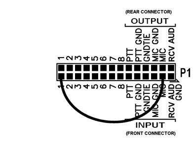
Figure 3
Then we would add a jumper for Microphone ground as follows:
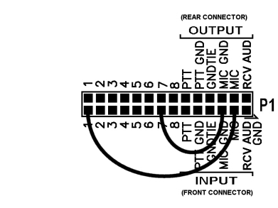
Figure 4
Following along with this logic, the OUTPUT side matching jumpering for the Microphone input and Microphone ground would be as follows:
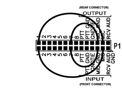
Figure 5
Then in like manner we will install the jumpers necessary for PTT and PTT ground as follows:
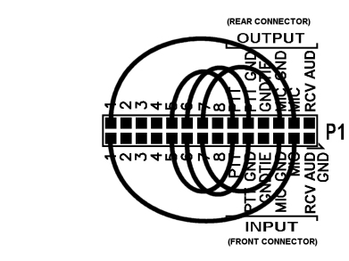
Figure 6
The remaining pins, 2, 3, 4 & 8 are not needed by the RIGblaster, but must be routed directly through the RIGblaster to the radio. Therefore we will install four straight through jumpers (referred to in the Ownrs Manual as Blue Shunt Jumpers) on these pins as follows:
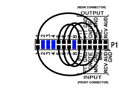
Figure 7
This then completes the jumpering necessary to use the RIGblaster on the IC-756PROIII and most other Icom radios with an 8 pin round microphone connector. Other radios, such as Yaesu and Kenwood, with 8 pin round microphone connectors would have different jumpering diagrams because they use different pin numbers in the microphone cable assigned for these functions.
Categories that this topic belongs to: RIGblaster Nomic, RIGblaster Duo, RIGblaster Plus, RIGblaster Plus II, RIGblaster Advantage, RIGblaster Pro, RIGblaster M8, RIGblaster M4, RIGblaster RJ