
Using DTMF for Remote Control
Jim Casamassa, WB9IXSArticle from the West Mountain Radio Quarter 3, 2020 Newsletter
A while back I purchased a new Flex 6500 and matching Maestro. My wife and I do a lot of camping and using the Maestro along with a Wifi hotspot is a great combination. However, I am not a fan of leaving my radio turned on 24/7 so I needed to find a way to turn the radio on and off remotely. At the same time I thought it would a good idea to disconnect the antennas when the system was off. So after some thought here is what I came up with.
Objectives:
1. Find a simple and reliable way to turn on / off the 12VDC power supply and the radio.
2. No computers running 24 / 7 in the shack
3. Disconnect the antenna(s) and ground them
Solutions:
1. Design and build a control that uses a touch tone decoder, DTMF with an embedded microcontroller to handle the overhead.
2. Build a remote 120VAC outlet box to plug the 12VDC power supply into.
3. Build a remote antenna disconnect box with grounding provisions.
One of the reasons I wanted the Flex Radio system and the Maestro was the fact that no computers are needed to operate the system. I did not want to add some remote application that would change that format.
DTMF or better known as touch tones has been around since the 60's. Every phone touch pad uses the same format and decoding the tones is done for you by using one of the DTMF decoder modules.
In this project I use the MT8870 decoder module. The first step is getting the tones into the decoder module. In my application I am using my house phone land line as the source for my connection. A simple 1:1 transformer across the phone line and a few components are all that is needed.
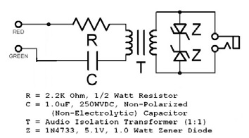
The audio is then fed into the decoder module where it is processed and a binary code is set for each digit sent. The next figure is the schematic for the MT8870. The decoded tones are brought out on pins 6-9 or Q4-Q1.

Looking at the next figure shows the decoded output for each key on the Touch Pad. If you use any of the keys from 0-9 or the # , * keys you only need to look at 4 pins on the MT8870 module. For example: To decode the number 6 key the binary code would be Q4=0 Q3=1 Q2=1 Q1=0. To decode the # key the binary code would be Q4=1 Q3=1 Q2=0 Q1=0.
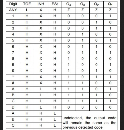
By following this table you can write your controller code to decode any combination you want. The following schematic is the controller circuit. The MCU is a PIC16F886. The code is written using a CCS compiler. West Mountain Radio is a wholly owned subsidiary of Custom Computer Services, Inc. (CCS, Inc.)
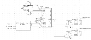
Here is a brief description of the circuit:
* Two pushbuttons to allow manual operation
* One output to control the radio on/off relay
* One output to control the AC outlet on/off relay and our inputs for the decoded data
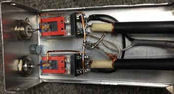
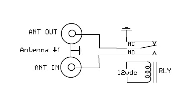
The following photos are an inside look at the antenna disconnect and grounding box. The relays are 12VDC and they are turned on as soon the main 12VDC power supply is active. When the relays are de-energized the incoming or antenna side is floating and the output or radio side is grounded. See the schematic for details. Here is the remote AC outlet. I took a standard 4" square box added a short line cord and a 120VAC relay. The relay acts just like a normal wall switch that turns on/off the power to the outlet. The controller switches the relay on/off per the code.

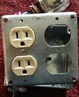
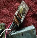
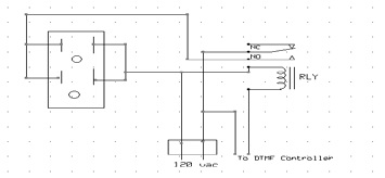
Here is the remote AC outlet. I took a standard 4" square box added a short line cord and a 120VAC relay. The relay acts just like a normal wall switch that turns on/off the power to the outlet. The controller switches the relay on/off per the code. The schematic is below the photos.
Here is how I use this gadget. When I get setup at the remote location and have the Maestro fired up I call my home and let the answering machine pickup the line. Then I send a series of tones (the programmed on tones) and hang up. The controller takes over from there. The way I have the code written the first thing that happens is the 120VAC outlet box is turned on. The 12VDC power supply that powers the radio and other equipment is plugged into this outlet. So now we have 12VDC being supplied to all the radio equipment. Oh yes, and the new antenna switch over box is now on, connecting the antennas to the system. A few seconds after the power is on, the radio relay is turned on. This allows the Flex radio to be remotely started without physically touching the button on the front panel. That's it...the radio fires up and the Maestro connects via the internet and I am on the air using my home station remotely.
At the end of my radio session I call my house phone and send a series of tones (the programmed off tones) and hang up. Now the process is reversed by the controller. The radio relay is de-energized and 15 seconds later the 120VAC outlet is shut off. Now the 12VDC is gone so the rest of the station equipment is off as is the new antenna box. This disconnects the antennas and grounds the input to the radio equipment.
My next phase of this is to decode tones that I will send via the Maestro and control my rotor and remotely turn on/off my amplifier. No computers needed or phone applications just simple equipment.
73
Jim
WB9IXS
Categories that this topic belongs to: More for Hams